 Mechanical engineering students are required to complete a senior design project. What follows are a few highlights of our group’s progress so far.
For a site devoted to the project, visit:
Bike Brake WordPress
Our project was to replace a traditional bicycle brake with a device which would slow the bike down, and capture energy into a battery. This is essentially a regenerative braking system for a bicycle.
We will capture braking energy (mechanical kinetic energy) into a battery (electrical potential energy). The battery is a portable USB battery, so it can charge anything with a USB plug.
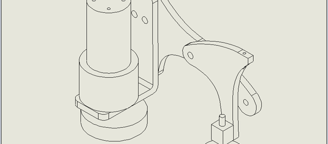
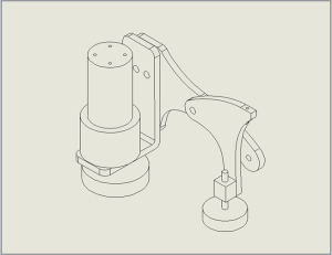
Below is an image of “prototype 2.5”. This device was designed in SolidWorks, 3D printed, and professionally fabricated out of aluminum. The result is what you see below. The traditional brake was removed and replaced with our device.
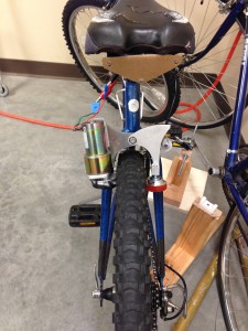
A DC generator is mounted on the left side which offers resistance to the rear wheel for braking, as well as capturing the tire kinetic energy and converting it into electrical energy. A “dummy wheel” is used on the right side of the tire to allow the brake to “squeeze” the side of the wheel (for traction, the generator wheel is difficult to turn, so it must be pressed hard against the side of the tire to get the generator to spin, which will slow the process in the meantime).
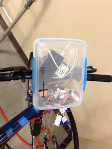
The “electronics box” houses the electronic components for our bicycle. The master switch turns on an Arduino, which collects data about the power output of the bicycle brake, as well as the speed of the bike, both with respect to time. This data is written to an SD card which may be removed, and the data may be analyzed. The arduino also controls LED “brake lights” which are mounted beneath the bicycle seat. (The lights turn on once a voltage is detected from the brake generator.)
A “reed switch” was used to capture the speed of the bicycle. This is the technology frequently implemented in bicycle speedometers. (A magnet opens or closes a switch each time the wheel rotates once)
Finally, the wires coming from the generator lead to a voltage regulator, which converts the wide range of power outputs from the generator into what our mobile battery can handle (5V and about 1 Amp).
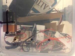
The 9V battery in the electronics box powers the Arduino. The Altoids box holds the Voltage Regulator (described above) and the black thing is our USB mobile battery. This is the battery that gets charged by braking.
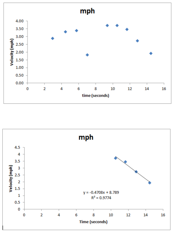
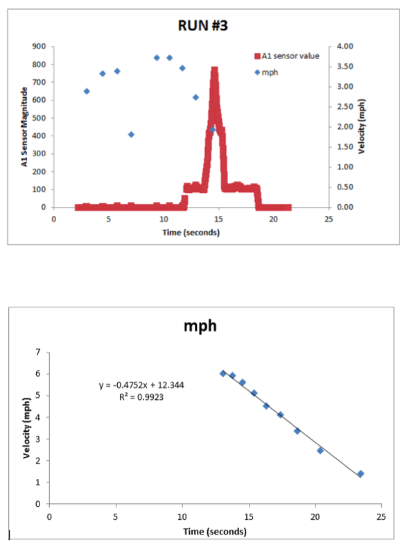
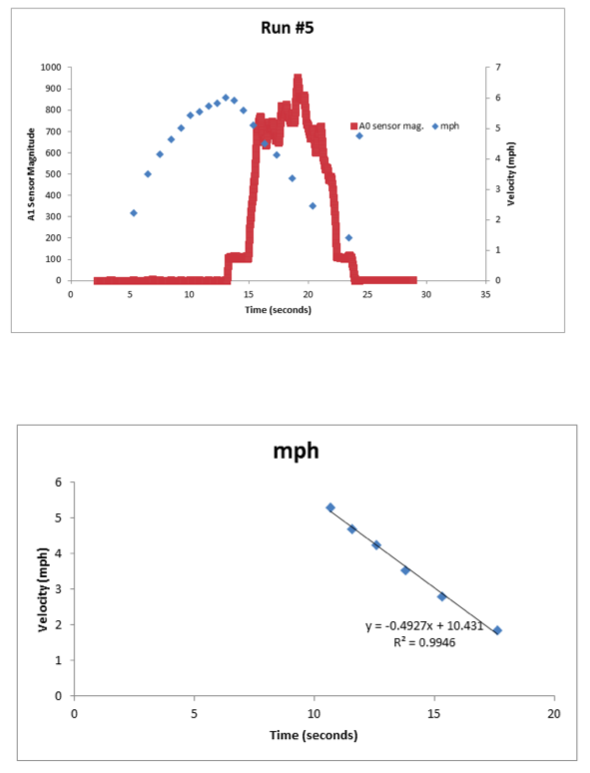
FINAL NOTES: As of this writing we were able to measure the deceleration caused by our device, HOWEVER, we could only collect voltage, and not measure current (something wasn’t working on test day). Thus, we do not have data for the amount of energy we are capturing with respect to time, BUT WE WILL SOON!
Also, Prototype 3 will be finished in a few weeks.
P.S. Below are some graphs developed from the initial testing of prototype 2.5:
For the next prototype (3.0):
Prototype 3.0
For the Arduino code:
Regenerative bike brake code